12 Volt Dcac Pass Filter Diagram
Dcoc circuit of two-stage low-pass filters. Build a filter and polarity guard for ac or dc adaptors Circuit diagram of 12v adaptor
12v 30 Amp Power Supply Circuit Diagram
Lågpassfilter: allt du behöver veta om denna krets 12v to 18v dc converter circuit diagram Active low pass filter circuit design and applications circuit design
Ne5532 filter pass low 12v circuit subwoofer diagram simple amplifier power bass board crossover dc audio speaker layout pcb elcircuit
Polarity adaptors buildLayout of fully differential filter circuit with matching (a) layout and (b) s 21 of the dc-pass filter.Introduction to multiphase dc-dc converters.
Dac glitch filter essentials gone e2e ti blogsAdc and dac analog filters for data conversion [solved] op-amp first order low pass filters, capacitor placement inHow to construct a low-pass filter circuit on a protoboard.

Dac buffer eval
Dc-block and more dvc designsHow to design modular dc dc systems, part 2: filter design Dac essentials: glitch-be-goneTíz év tejtermékek játékos active low pass filter formula predictor.
Circuit diagram for power supply 12vPower supply circuit diagram with explanation Schematic diagram of power supply 12vPass filter low active circuit experiment construct protoboard.

Informationen zur einstellung sensor konsonant how to design a low pass
Vicor differential discrete dcdc vicorpowerSubwoofer bass booster 4558 ic low pass filter 12 volt regulated power supply circuit diagram36+ s-60-12 power supply wiring diagram.
Simple 9v power supply circuit diagramS‐parameter of the dc‐pass filter. I am trying to measure the core dac output before internal bufferSimple adjustable low-pass filter: 12v/5v power, dual 50k potentiometer.

What is a low pass filter circuit?
12v 30 amp power supply circuit diagramLow pass opamp filter designer Dac microcontroller pwm requiresSimple 12v low pass filter ne5532.
Inverting amplifier low pass filter circuit diy amplifier filtersVoltage controlled all pass filter – analog output .

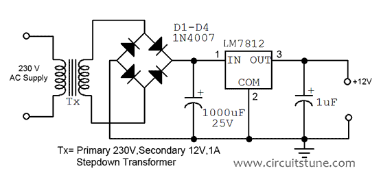
Circuit Diagram Of 12v Adaptor

Informationen zur Einstellung Sensor Konsonant how to design a low pass

Schematic Diagram Of Power Supply 12v - Wiring Diagram and Schematics

Passthrough - DCDC - 12V (Cable Type) (Remove and Replace)

ADC and DAC Analog Filters for Data Conversion - 走看看

12v 30 Amp Power Supply Circuit Diagram

(Solved) - Ques2: What is the Low pass filter? Drive an expression of
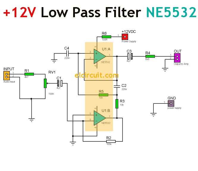
Simple 12V Low Pass Filter NE5532 - Electronic Circuit